Preparing an Output Board
Contents
There are three ways to prepare a trigger-output board:
Write a sketch to Arduino UNO (or its clone)
Write a sketch to Arduino Leonardo (or its clone)
(Optimal) Flash the
Arduino-fasteventserverkernel to Arduino UNO (or its clone)
Before starting, make sure about the path to your Arduino board.
Writing a sketch to Arduino UNO
Although this may add a 1-2 ms overhead to the output latency, this is probably the simplest way. Any UNO clone (including Nano clones) should work.
Find the
SimpleArduinoOutputsketch from thelibrariesdirectory of the repository.Using the Arduino app, compile and write the sketch to your UNO clone.
To use this type of output boards, select uno as the “driver type” of FastEventServer.
By default, the trigger output comes out of the pin GPIO13 (LED).
Writing a sketch to Arduino Leonardo
Leonardo- and Micro- clones fall into this category. Boards of this type may also add a 1-2 ms overhead to the output latency.
Find the
SimpleArduinoOutputsketch from thelibrariesdirectory of the repository.Using the Arduino app, compile and write the sketch to your Leonardo clone.
To use this type of output boards, select leonardo as the “driver type” of FastEventServer.
By default, the trigger output comes out of the pin GPIO13 (LED).
Flashing Arduino-fasteventoutput to a UNO clone
This method makes use of the arduino-fasteventtrigger project.
Use the leonardo driver to use a board of this type from FastEventServer.
By using this method, the trigger-output latency will go down to the sub-millisecond order. Nevertheless, it takes some additional procedures to follow.
Caution
arduino-fasteventoutput, in reality, will only make use of the serial-to-USB conversion tip on the UNO (i.e. ATmega16U2).
This means:
Make sure that your UNO clone has the ATmega16U2 as its converter chip.
Other USB-based boards that uses the ATmega16U2 chip may work (not recommended nor supported).
To flash a kernel to ATmega16U2, we need to turn the chip into the “Device Firmware Update” (DFU) mode, by which you can send the kernel data directly through the USB cable. You can learn more about the DFU mode here on the official website.
First find the Arduino-fasteventoutput.hex binary from the libraries directory of the Pose-Trigger repository. The rest of the procedures are as follows:
Install ``dfu-programmer``: e.g. on Ubuntu, it can be simply done by running
sudo apt-get dfu-programmer.Put the UNO board into the DFU mode, being left connected to the computer:
for UNO rev. 2 and later, the board can be put into the DFU mode by briefly connecting the RESET and GND pins of the 6-pin header connected to the ATmega16U2 chip. The image below shows the positions of the RESET and GND pins (and their 6-pin header):
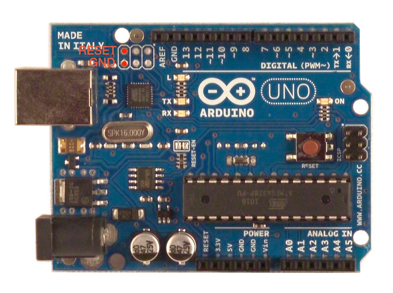
The location of the
RESETand theGNDpins¶Note
After going into the DFU mode, the path to the UNO device will disappear from the “/dev” directory (so don’t worry about it).
Erase the previous kernel: run
sudo dfu-programmer atmega16u2 erase.Write out our kernel: run
sudo dfu-programmer atmega16u2 flash Arduino-fasteventoutput.hex.Reset (re-boot) the UNO: run
sudo dfu-programmer atmega16u2 reset.Check that the UNO board appears again under the
/devdirectory.
After the procedures, you can use the board as the leonardo-type output board.
The trigger comes out of the PB1 pin of the 6-pin ATmega16U2 header:
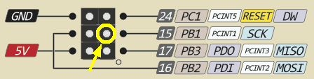
The location of the PB1 pin.
Note
By writing fasteventoutput to the Arduino board, it cannot be used any more as an Arduino.
In case you want to “resume” the Arduino functionalities, write back the official Arduino firmware using dfu-programmer again by following the same procedures.
Testing the board using the serial commands
You can test the boards by sending the single-character commands without launching FastEventServer (e.g. through the serial monitor of the Arduino app).
The setting of the console:
Serial port: Your Arduino board
Baud rate: 230400 baud (it matters only when you use the sketch)
Newline: “No line ending” (the board ignores the newline characters anyway)
Name |
Character |
Description |
|---|---|---|
|
|
Set the output to LOW |
|
|
Set the output to HIGH |
Note that the command characters themselves do not really mean HIGH/LOW. On the side of the output board, in reality, it applies the bit flag 0x04 to the command to determine the output.